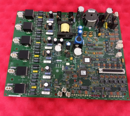
IS200EHPAG1ABB GE EXCITER GATE PULSE AMPLIFIER BOARD
General info
| Manufacture | GE |
| Item No | IS200EHPAG1ABB |
| Article number | IS200EHPAG1ABB |
| Series | Mark VI |
| Origin | United States(US) |
| Dimension | 85*11*110(mm) |
| Weight | 1.1 kg |
| Customs Tariff Number | 85389091 |
| Type | EXCITER GATE PULSE AMPLIFIER BOARD |
Detailed data
IS200EHPAG1ABB GE EXCITER GATE PULSE AMPLIFIER BOARD
The is200ehpag1a is part of the ex2100 series. The action of the pulse amplifier is to directly control the silicon controlled rectifier (scr).
These plug connectors vary in their selection and number. 8 of them are double, 4 are 4 and 2 are 6. The connector is located in the upper right corner of the circuit board near the four stands and can be used as a panel accessory.
The power conversion cabinet contains the power conversion module (PCM), the excitation gate pulse amplifier (EGPA) board, the AC circuit breaker and the DC contactor. The three-phase power supply to the PCM comes from the PPT outside the exciter. The AC power enters the cabinet through the AC circuit breaker (if powered) and is filtered by the three-phase line filter in the auxiliary cabinet.
Manual Power Disconnect (Optional)
The manual air circuit breaker disconnect switch is a disconnect device between the supply voltage transformer secondary and the static exciter. It is a molded case, three-phase, non-automatic, panel mounted switch that is manually operated to isolate the AC input power. It is a no-load disconnect device.
Power Conversion Module (PCM)
The exciter PCM includes the bridge rectifier, DC leg fuses, thyristor protection circuits (e.g., dampers, filters, and fuses), and leg reactor components. Depending on the required power output, the components will vary for different bridge ratings.
Bridge Rectifiers
Each bridge rectifier is a 3-phase full-wave thyristor bridge, as shown in Figure 2-3, consisting of 6 SCRs (thyristors) controlled by an Excitation Gate Pulse Amplifier board (EGPA). Heat is dissipated by large aluminum heat sinks and forced airflow from overhead fans.
Leg Reactors and Cell Snubbers
Commutating reactors are located in the AC legs supplying the SCRs, and the dampers are RC circuits from the anode to the cathode of each SCR. The cell dampers, line-to-line dampers, and line reactors perform the following functions together to prevent erroneous operation of the SCRs.
-Limit the rate of change of current through the SCRs and provide a current ramp to help initiate conduction.
-Limit the rate of voltage change between cells and limit the reverse voltage that occurs between cells during cell commutation.
SCR arresters include PRV resistors to limit peak reverse voltage. These resistors can be removed if necessary
Three-phase input power is fed from the secondary of the PPT to the bridge rectifier, either directly or through an AC circuit breaker or disconnect switch and line-to-line filters. With an inverting bridge rectifier design, the bridge rectifier is able to apply a negative voltage, providing a fast response for load rejection and de-excitation. The DC current output of the bridge rectifier is fed through a shunt and, in some designs, through a contactor (41A or 41A and 41B) into the generator field. Bridge rectifier designs use DC leg fuses to protect the SCRs from overcurrent.


