GE IS200CABPG1BAA Control Assembly Backplane Board
General info
| Manufacture | GE |
| Item No | IS200CABPG1BAA |
| Article number | IS200CABPG1BAA |
| Series | Mark VI |
| Origin | United States(US) |
| Dimension | 180*180*30(mm) |
| Weight | 0.8 kg |
| Customs Tariff Number | 85389091 |
| Type | Control Assembly Backplane Board |
Detailed data
GE IS200CABPG1BAA Control Assembly Backplane Board
Functional Description:
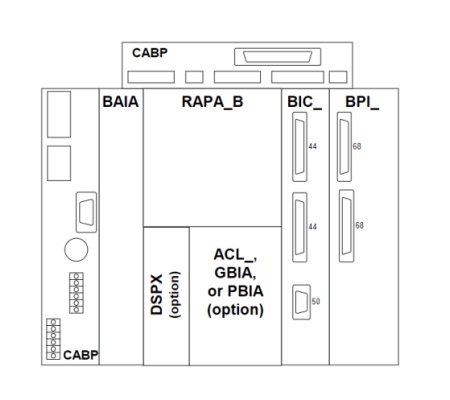
The IS200CABPG1BAA is a Control Assembly Backplane developed by GE. It is part of the Drive Control Series. The Control Assembly Backplane (CABP) board is a key component in the complex architecture of the innovative series drive system. As a multi-layer printed circuit board, its primary function revolves around facilitating the seamless interconnection required for the various printed circuit boards plugged into it, while also acting as a conduit for critical external signal interfaces.
Bridge Interface Board (BAIA) This board facilitates basic bridge interface functions that are critical to the operation of the system. Auxiliary Genius Interface Module (GBIA), Auxiliary Profibus Interface Module (PBIA), or Application Control Layer Board (ACL) These boards enhance the system's capabilities in auxiliary control and interface tasks to meet a variety of operational needs. Digital Signal Processing Control Board (DSPX) This optional board provides advanced digital signal processing capabilities that enhance the functionality of the system. Rack Power Board An integrated part of the management system's power distribution, ensuring efficient and reliable power delivery. Bridge Interface Board Another variation of the Bridge Interface Board that provides system configuration flexibility. Drive Bridge Personality Interface Board (BPI_) or Bridge Interface Board (FOSA)These boards facilitate seamless interaction between the drive and its associated bridge personality, thereby optimizing performance.
Hardware Features:
The terminal blocks associated with the user input/output (I/O) function boards are strategically placed near the entry point where the application cables enter the cabinet. This placement ensures easy access and efficient connections in the system setup.
Electrical connections to these terminal blocks are made through two different multi-core cables that are carefully isolated to meet different voltage requirements. One cable is dedicated to low voltage applications (less than 50 volts), while the other cable is dedicated to high voltage applications (greater than 50 volts).
The design of the circuit board takes meticulous measures to prevent incorrect connections and prevent operational accidents. Non-circuit board connectors are carefully designed with multiple methods to prevent incorrect insertion of multiple connector types, and different types of connectors are used for each different function, ensuring compatibility and preventing incorrect connections.
Each connector has unique keying, which ensures that the connector only fits into its designated socket, eliminating the possibility of incorrect insertion.
Similar connectors are adequately spaced to make incorrect insertion physically impossible. This spatial arrangement enhances operational safety and reduces the possibility of inadvertent errors.
The connectors used on the circuit board meet strict integrity and compatibility standards, further improving the reliability and robustness of the system. These connectors follow one of the following principles
Each connector is individually keyed to its corresponding socket, ensuring precise alignment and secure connection.
Similar modules use different connector sizes, such as 96-pin vs. 128-pin variants, ensuring clear differentiation and preventing interchangeability issues.
Modules have a common pinout between compatible connectors, allowing for seamless interchange without damage or operational hindrances.

Frequently asked questions about the product are as follows:
-Is the IS200CABPG1BAA backplane compatible with other models of GE control components?
The IS200CABPG1BAA backplane is designed for a specific series of GE control components and has poor compatibility with other models. There are differences in electrical interfaces, signal transmission protocols, etc. between different models of control components. Random mixing may cause the system to not work properly or communication failures.
-What impact does the IS200CABPG1BAA backplane have on system performance?
As the core connection component of the control component, the performance of the backplane directly affects the overall performance of the system. If the transmission bandwidth of the backplane is insufficient, data transmission delays may occur, affecting the real-time performance and response speed of the system; if the stability of the backplane is not good, there will be problems such as failures or signal interference, which will reduce the reliability of the entire control system and may even cause system downtime.
-Can the IS200CABPG1BAA backplane be upgraded?
Generally speaking, GE will upgrade and optimize the backplane according to technological development and user needs. However, for the installed IS200CABPG1BAA backplane, whether it can be upgraded depends on the specific equipment architecture and compatibility. When considering an upgrade, you need to consult GE's technical support staff or professional engineers to evaluate the feasibility and necessity of the upgrade, and strictly follow the upgrade guide to ensure that the upgraded system can operate stably.


