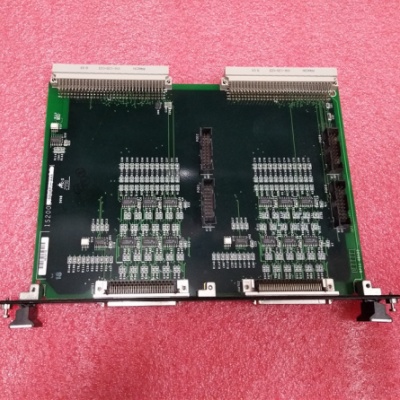
GE IS200BPIIH1AAA Bridge Power Interface Board
General info
| Manufacture | GE |
| Item No | IS200BPIIH1AAA |
| Article number | IS200BPIIH1AAA |
| Series | Mark VI |
| Origin | United States(US) |
| Dimension | 180*180*30(mm) |
| Weight | 0.8 kg |
| Customs Tariff Number | 85389091 |
| Type | Bridge Power Interface Board |
Detailed data
GE IS200BPIIH1AAA Bridge Power Interface Board
The IS200BPI Bridge Power Interface Board (BPIl) is a bridge power interface using integrated gate commutated thyristor (IGCT) switch devices. The board occupies connectors J16 and J21 of the IS200CABP Cable Assembly Backplane (CABP) in the Innovation Seriesrm Board Rack.
The BPIl board is used to relay 24 gate firing commands and 24 gate status feedback signals between the IS200BICI Bridge Interface Control Board (BICI) and two remotely mounted IS200GGX1 Expander Load Source Boards (GGXI). The GGXI board translates the firing and status commands between these signals and a fiber optic interface to access the gate driver modules located in the bridge.
The BPIl board is designed to interface with and complement the BICI board. The BPI board connects to the BICI board via the InnovationSeriesrm Board Rack Backplane. The front card connectors on both boards connect to the GGXI board. Connected to the GGXI board via fiber optics, high voltage isolation is provided for the BPI and BICI boards. Voltage feedback isolation is provided by attenuation from the DS200NATO voltage feedback scaling board (NATO).
The BPIl board uses standard RS-422 drivers and receivers for differential point-to-point signaling. If there is no connection to a given receiver (cable disconnected), the receiver will default to a bad gate signal state.
The BPII board incorporates a serial prom identification chip that is connected to a board identification bus line (BRDID). The BPII board supplies pull-upresistors to P5 and the returns to DCOM for theBRDID line. The pull-up signal passes through to the GGXI board (s) that forward it on to the NATO boardwhere it is connected to chassis. This indicates that allcables along this path are connected. The return(DCOM) can be used by other boards in the path to determine if they are connected to the BPIl board.Alternatively, the GGXI board can use an opto-coupleroutput connected across these signals to indicate that the cable is plugged in.
The BPIl board supplies opto-isolation to detect that the correct BICI and BPIl board cable pairs are plugged into the GGXI board. To verify that the GGXI board(s)is properly connected, a pair of wires in thePFBK cable going from the BICI board to the GGXboard and in the JGATE cable going from the GGXlboard to the BPIl board are dedicated. To verify that the cables are not crossed, current is passed in opposite directions for the first and second GGXI boards. Asignal showing that the current(s) has been detected in the correct direction is passed back to the BICI boardfrom the BPIl board, See Figure l for a diagram of this.

Frequently asked questions about the product are as follows:
-What are the functions of the GE IS200BPIIH1AAA Bridge Power Interface Board?
The IS200BPIIH1AAA Bridge Power Interface Board provides power to connected devices/modules. Facilitates data transfer between the system and external modules. Provides diagnostic information and status indicators (typically via LEDs). Ensures safe and reliable operation by managing power and communication integrity.
-What devices and modules does the IS200BPIIH1AAA interface with?
Manages input and output operations. Sensors, actuators, and other industrial field devices. The board facilitates communication between the control system and other external devices. Includes other interface boards, power supplies, and host controllers.
-What are the technical specifications of the IS200BPIIH1AAA?
24V DC or specified voltage, depending on system configuration.
Depending on the setup, it may include serial, Ethernet, or other communication protocols.
Designed to fit into specific chassis slots (refer to system manual).
Typically includes status LEDs that show power, communication, and error status.
Typically intended for industrial environments where temperature, humidity, and vibration are a concern.


